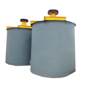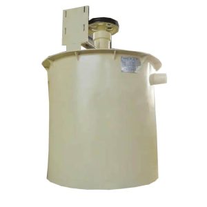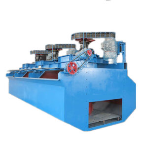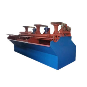
XCF/KYF Flotation Cell
Capacity: 0.2~50 m³/min
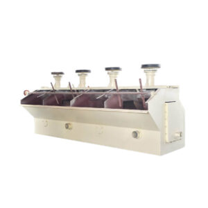
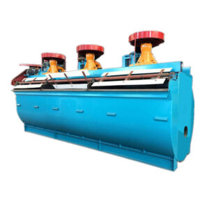
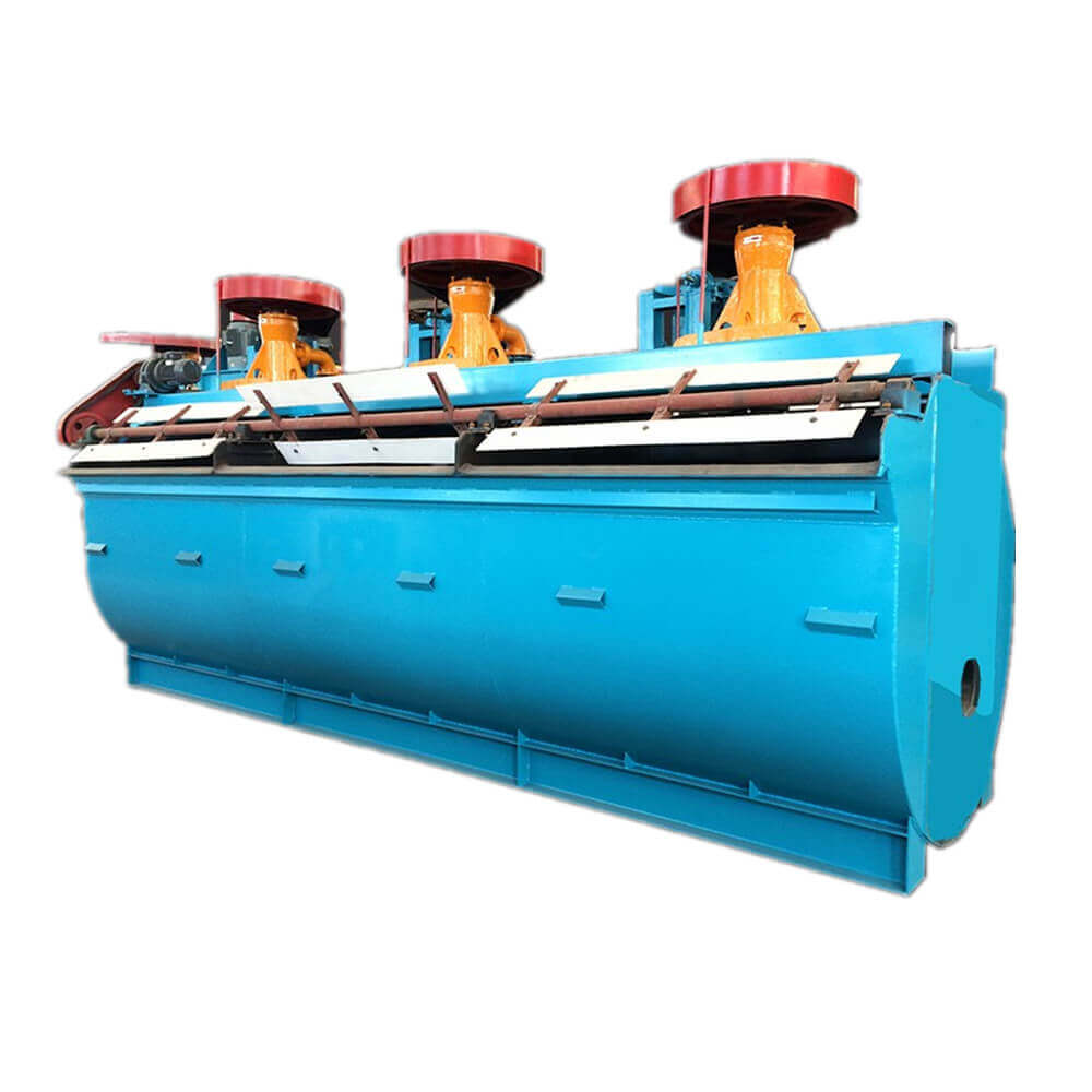
CXF flotation machine is an air inflation mechanical agitation flotation cell with slurry suction.
KYF flotation machine is an air-inflation mechanical agitation flotation cell without slurry suction.
XCF/KYF Flotation Cell/Machine Overview
Flotation machines constitute the basic equipment for useful minerals recovery from non-ferrous ores and other raw materials by flotation. They can operate also as individual flotation cells.
Flotation Cells (Froth Flotation) were developed to separate and recover high-value Sulphide ores from low-grade ore bodies. The Flotation Cell is aerated to produce bubbles and agitated to keep the solids particles in suspension in the pulp. A flotation cell is an appliance in which froth flotation of ores is performed. It has provisions for receiving conditioned pulp, aerating this pulp, and for separate discharge of the resulting mineralized froth and impoverished tailings.
Flotation Cells/Machines Types
- Agitating flotation machine
- Self-priming flotation machine
- Aeration flotation machine
- Flotation column machine
Flotation Cells/Machines For Sale
Our froth flotation separation is sold all around the world and is popular with clients. The models of our flotation cells are main including SF, XJK, JJF, XCF, and KYF flotation cells.
Advantages
XCF/KYF Flotation Cell Advantages
- Simple structure and strong stirring capacity.
- The air is evenly dispersed. The air and slurry combination is fine.
- Fewer tailings deposits, low peripheral speed, and low energy consumption.
- Light wear of quick-wear part with a long working life.
- Mechanical agitation, without self-air-inflation and self-priming pulp. The ladder configuration between the workroom is essential.
- The structure features of the XCF flotation cell are similar to the KYF flotation cell. The difference is that a stator is specially provided above the impeller to form a special negative pressure zone, self-priming pulp.
- KYF and XCE flotation cells can be combined use.
Structures & Working Principle
XCF/KYF Flotation Cell/Machine Structure
XCF/KYF flotation machine is composed of a tank, a large isolation plate impeller with top and bottom blades, a seat stator radial blade, a split disc cover, a split center tube, a connecting tube with air-bleed hole, a bearing body, hollow main shaft, and the air adjustable valve.
XCF/KYF Flotation Cell/Machine Working Principle
When the flotation machine is at work, the rotation of the impeller makes the slurry all-around via the tank bottom absorbed from the downside of impelled into inner-vanes of the impeller, where low-pressure air is produced by the blower goes into via hollow shaft and the air distributor of impeller chamber at the same time. After a full mixture of the slurry and air among vanes, they are pushed out in the inclined upward direction from the upper half of the impeller around and go into the tank via steady flow and orientation by the stator. Air bubbles rise to the foam stability area, and after the concentration process, the froths overflow from the overflow weir into the froth tank. Another part of the slurry flows toward the lower part of the impeller, then through the impeller agitation, they are mixed to form mineral-laden bubbles again, and the rest of the slurry will flow to the next tank to become tailings eventually.
Technical Parameters
| Model | Volume (m3) | Capacity (m3/min) | Impeller Diameter (mm) | Impeller Speed (r/min) | Power(kW) | Singe Cell Weight (kg) | |
| For Stirring | For Scraper | ||||||
| XCF-1 | 1 | 0.2 -1 | 400 | 358 | 5.5 | 1.1 | 1154 |
| XCF-2 | 2 | 0.4 -2 | 470 | 331 | 7.5 | 1659 | |
| XCF-3 | 3 | 0.6 -3 | 540 | 266 | 11 | 1.5 | 2259 |
| XCF-4 | 4 | 1.2 -4 | 620 | 215 | 15 | 2669 | |
| XCF-8 | 8 | 3.0 -8 | 720 | 185 | 22 | 3958 | |
| XCF-16 | 16 | 4-16 | 860 | 160 | 37 | 6520 | |
| XCF-20 | 20 | 5-10 | 910 | 155 | 45 | 9200 | |
| XCF-24 | 24 | 4-24 | 950 | 153 | 55 | 9660 | |
| XCF-30 | 30 | 7-15 | 1000 | 141 | 55 | 14810 | |
| XCF-38 | 38 | 10 -38 | 1050 | 136 | 55 | 17000 | |
| XCF-40 | 40 | 10-38 | 1050 | 138 | 75 | 17500 | |
| XCF-50 | 50 | 10-25 | 1120 | 110 | 90 | 22000 | |
| XCF-70 | 70 | 13-50 | 1200 | 103 | 90 | 26200 | |
| Model | Volume (m3) | Capacity (m3/min) | Impeller Diameter (mm) | Impeller Speed (r/min) | Power(kW) | Singe Cell Weight (kg) | |
| For Stirring | For Scraper | ||||||
| KYF-1 | 1 | 0.2-1 | 340 | 281 | 4 | 1.1 | 826 |
| KYF-2 | 2 | 0.4-2 | 410 | 247 | 5.5 | 1419 | |
| KYF-3 | 3 | 0.6-3 | 480 | 219 | 7.5 | 1.5 | 1885 |
| KYF-4 | 4 | 1.2-4 | 550 | 200 | 11 | 2206 | |
| KYF-8 | 8 | 3.0-8 | 630 | 175 | 15 | 3600 | |
| KYF-16 | 16 | 4.0-16 | 740 | 160 | 30 | 5900 | |
| KYF-20 | 20 | 5-20 | 780 | 155 | 37 | 8240 | |
| KYF-24 | 24 | 4.0-24 | 800 | 150 | 37 | 8540 | |
| KYF-30 | 30 | 7-30 | 900 | 141 | 45 | 13820 | |
| KYF-38 | 38 | 10-38 | 880 | 139 | 45 | 16500 | |
| KYF-40 | 40 | 10-38 | 950 | 138 | 55 | 17000 | |
| KYF-50 | 50 | 10-40 | 1030 | 120 | 75 | 22000 | |
| KYF-70 | 70 | 13-50 | 1120 | 110 | 90 | 26200 | |

