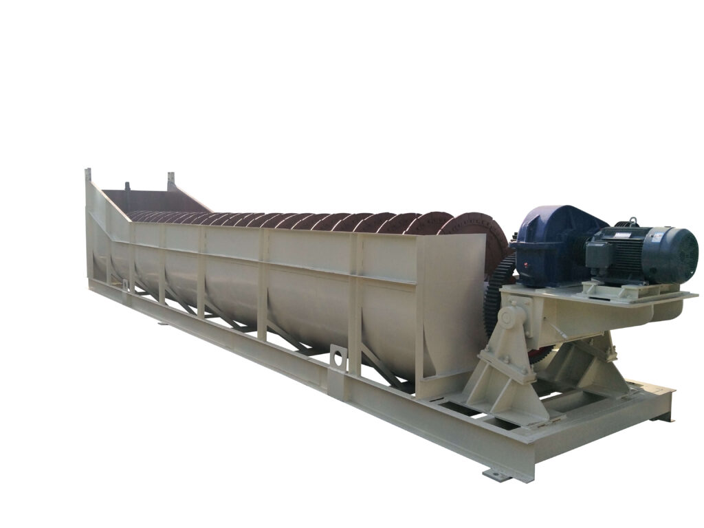
Spiral Classifier
Capacity: 21-1785 T/24h
Moto Power: 3-44 Kw
Spiral Diameter: 300-3000 mm
Process Material: Natural sand, artificial sand, machine-made sand.
Spiral Classifier Overview
Spiral Classifier For Sale
Our Spiral Classifier is available with spiral diameters up to 120″. These classifiers are built in three models with 100%, 125% and 150% spiral submergence with straight side tanks or modified flared or full flared tanks. The single, double or triple pitch spirals are available.
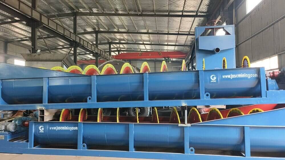
The spiral classifier is one of the size-classifying equipment for the mining industry. It is a kind of equipment for mineral classification based on the principle that the specific gravity of solid particles and the speed of precipitation in the liquid is different. It can filter the material powder from the mill, then screw the coarse material into the mill inlet with the spiral slice, and discharge the filtered fine material from the overflow pipe. Spiral classifier is short for the classifier. The classification machine mainly has the high weir type single screw and the double screw, the sinking type single screw, and the double screw four kinds of classification machines. The classifier mainly comprises a transmission device, a spiral body, a trough body, a lifting mechanism, a lower bearing (Bush), and a discharge valve. Spiral classifier is widely used in mineral processing plants with a ball mill as a closed-circuit circuit to separate the flow of ore sand, or used in gravity concentrators to grade ore sand and fine mud, and metal beneficiation processes to grade the size of ore pulp and washing operations in the desliming hopper, dehydration and other operations.
Advantages
Spiral Classifier Advantages
- Low power consumption
- Heavy-duty, long working life
- Powerful self-contained spiral lifting device
- Continuous spiral raking
- High classifying efficiency
- Wide choice of weir height
- Rigid tank and substructure
- Wide choice of tank design
- A wide range of industries serviced
Structures & Working Principle
Spiral Classifier Structure
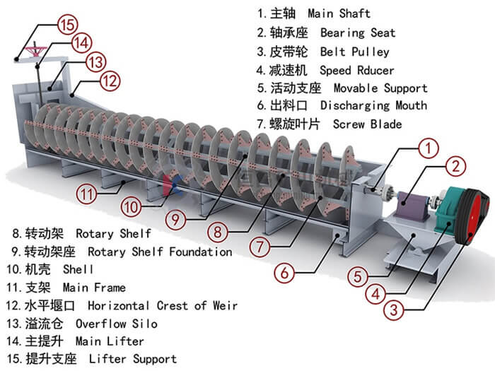
Spiral Classifier Working Principle
The grinded pulp is fed into a tank from the inlet in the middle of settlement region, and the slurry classification sedimentation area is under the inclined tank. The spiral with low-speed rotation stirs the slurry, so that the fine particles rise, and the coarse particles sink to the bottom of the tank. The overflow dam is above the bearing center which is under the screw shaft, and is underneath the overflow end.
Technical Parameters
| Model | Spiral Diameter (mm) | Spiral Speed (r/min) | Tank | Process Capacity (t/24h) | Drive Motor (kw) | Lift Motor (kw) | |||
| L(mm) | W(mm) | Slope(°) | Over Flow | Returned Sand | |||||
| FG-5 | Φ500 | 9.2 | 3900 | 560 | 10.5°-14° | 21-75 | 145-260 | 3 | 0 |
| FG-7 | Φ750 | 7.8 | 5367 | 830 | 10.5°-14° | 65-154 | 255-564 | 3 | 0 |
| FG-10 | Φ1000 | 7 | 6500 | 1110 | 10.5°-14° | 85 | 473-1026 | 5.5 | 0 |
| FG-12 | Φ1200 | 5, 6, 7 | 6500 | 1372 | 10.5°-14° | 150 | 1145-1600 | 5.5 | 2.2 |
| FG-15 | Φ1500 | 2.5, 4, 6 | 8265 | 1664 | 14°-18.5° | 235 | 1140-2740 | 7.5 | 2.2 |
| FG-20 | Φ2000 | 5.4 | 8400 | 2396 | 14.5°-18.5° | 400 | 5940 | 15 | 2.2 |
| FG-24 | Φ2400 | 3.6, 5.4, 6.3 | 9160 | 2600 | 14°-18.5° | 580 | 6800 | 11/15 | 2.2 |
| FG-30 | Φ3000 | 3.17 | 12500 | 3200 | 14°-18.5° | 890 | 11650 | 22 | 4 |
| 2FG-12 | Φ1200 | 5, 6, 7 | 6500 | 2620 | 14°-10.5° | 300 | 2290-3200 | 5.5 x 2 | 2.2 x 2 |
| 2FG-15 | Φ1500 | 2.5, 4, 6 | 8265 | 3200 | 14°-18.5° | 460 | 2240-5360 | 7.5 x 2 | 2.2 x 2 |
| 2FG-20 | Φ2000 | 5.4 | 8400 | 4296 | 14.5°-18.5° | 800 | 11880 | 15 x 2 | 2.2 x 2 |
| 2FG-24 | Φ2400 | 3.6, 5.4, 6.3 | 9160 | 5040 | 14°-18.5° | 1160 | 13600 | 11 x 2 / 15 x 2 | 2.2 x 2 |
| 2FG-30 | Φ3000 | 3.17 | 12500 | 6300 | 14°-18.5° | 1785 | 23300 | 22 x 2 | 4 x 2 |

