Home » Equipment » Magnetic Separation Equipment » Slurry Magnetic Separator
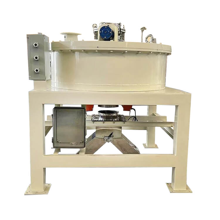
Slurry Magnetic Separator
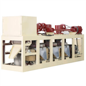
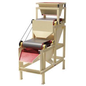
The slurry magnetic separator is a magnetic separation device designed specifically for processing high-water-content mineral slurries. It efficiently separates magnetic materials using a strong magnetic field in a wet environment, making it particularly suitable for processing mineral slurries with fine particle size and high mud content.
Capacity: 10-100 m3/h
Feeding Material Density: 10-30%
Power: 90-178 kW
Application: Ceramics, mining, chemical industry, electronics, food, and other industries.
Slurry Magnetic Separator Overview
The slurry magnetic separator is a kind of equipment widely used in mining, metallurgy, environmental protection, and other fields. It is mainly used to separate and extract magnetic substances. Its working principle is mainly based on the adsorption effect of magnetic fields on magnetic substances.
Application Range
The slurry magnetic separator is widely used in the removal and separation of iron impurities and magnetic substances in slurries. It glazes in ceramics, glass, chemicals, electronics, food, medicine, and other industries.
Features
- Unique material reverse pressure flow direction design, so the larger the specific gravity of iron, the easier to remove.
- The design of the pressure flow direction makes iron adsorbed and self-resistant, and it is easier to be left in the magnetic field.
- The back-flushing type automatic iron-unloading system is designed so that the iron can be more easily, quickly, and thoroughly discharged to the machine body.
- The equipment comes with an automatic water storage system, through the intelligent system’s accurate control, realizes the minimum water consumption, more energy saving, and environmental protection.
- In particular in the food and drug industry, the material contact part is made of food-grade stainless steel, so as to avoid secondary pollution.
- The equipment welding adopts high-tech non-filling cold welding technology and high-light treatment of the inner wall. Avoid material residue and wall hanging phenomenon.
Advantages
The slurry magnetic separator offers superior performance with a high and evenly distributed magnetic field, ensuring effective iron removal. It features an advanced cooling system that utilizes internal oil circulation and external water-oil heat exchange through a heat exchanger, maintaining a temperature rise of around 20°C to prolong the lifespan of the electromagnetic coil. The durable brake valve, made of high-quality imported materials, ensures a tight seal with no slurry leakage. High-pressure water flushing and air blowing guarantee thorough, residue-free cleaning, while the special mesh material eliminates residual magnetism when powered off, simplifying iron removal. Designed for fully automatic operation, the separator eliminates the need for manual supervision, providing fast, efficient, and residue-free iron removal.
- High Adaptability: Designed specifically for slurries, it can handle slurries with solids content ranging from 5% to 40%.
- High-Efficiency Separation: Utilizes rare earth permanent magnets or electromagnetic designs, achieving magnetic field strengths of 0.2-1.2T.
- Automatic Slag Discharge: Equipped with an automatic scraper system to ensure continuous operation without clogging.
- Modular Design: Multiple magnetic separation units can be flexibly combined to suit the processing volume.
- Corrosion-Resistant Construction: Contact parts are made of 304/316 stainless steel or polyurethane coating.
Structures & Working Principle
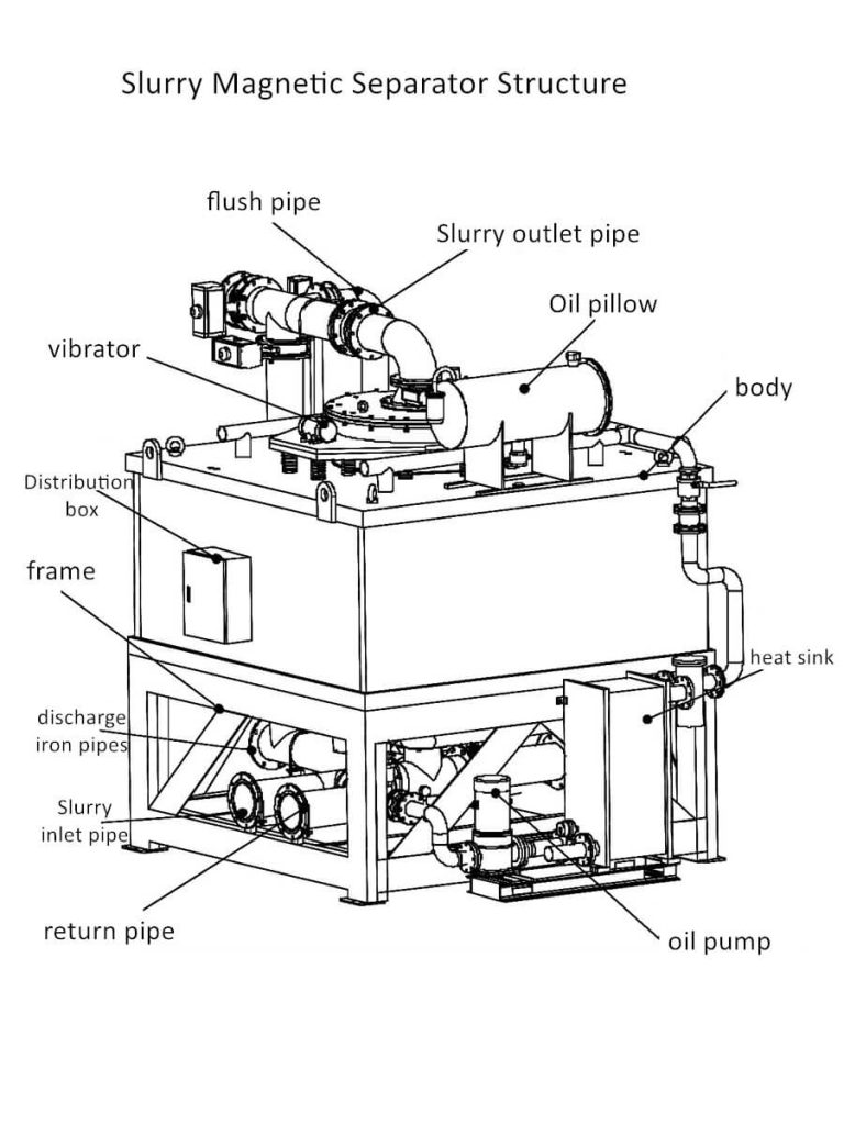
Slurry Magnetic Separator Structure
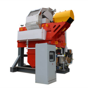
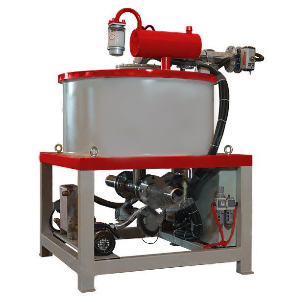
The slurry magnetic separator is mainly composed of a magnetic system, tank body, transmission device, ore feeding device, flushing device, and other parts. Among them, the magnetic system is the core part of the device and is responsible for generating the magnetic field. The tank is used to accommodate the slurry to be processed and achieve separation of magnetic substances through the action of a magnetic field.
Slurry Magnetic Separator Working Principle
During the working process, the electromagnetic slurry magnetic separator will form a stable magnetic field. When the slurry containing magnetic substances enters the magnetic field area, it is affected by the force of the magnetic field, and the magnetic substances are adsorbed on the surface of the magnetic system. Non-magnetic materials, on the other hand, will continue to flow along the tank because they are not affected by the magnetic field force, thereby achieving the separation of magnetic materials and non-magnetic materials.
The magnetic system usually consists of electromagnets and magnetic poles. Electromagnets generate magnetic fields through electric current, and the magnetic poles determine the distribution and intensity of the magnetic field. By adjusting the size and direction of the current, the strength and distribution of the magnetic field can be controlled to meet different separation needs.
Technical Parameters
| Model | ZT-YL600-Q | ZT-YL800-Q | ZT-YL1000-Q | ZT-YL1000-T | ZT-YL1000L-Q | ZT-YL1200-Q | ZT-YL1200L-Q |
| Input Voltage (ACV) | 380 | 380 | 380 | 380 | 380 | 380 | 380 |
| Power (kW) | 90 | 120 | 150 | 140 | 150 | 178 | 178 |
| Magnetic Field Strength (GS) | 18000 | 18000 | 18000 | 15000 | 18000 | 15000 | 15000 |
| Capacity (m3/h) | 10-40 | 15-50 | 20-75 | 20-75 | 20-75 | 25-100 | 25-100 |
| Kaolin Feed Concentration | 10-20% | 10-20% | 10-20% | 10-20% | 10-20% | 10-20% | 10-20% |
| Potassium, Albite Ore Concentration | 20-30% | 20-30% | 20-30% | 20-30% | 20-30% | 20-30% | 20-30% |
| Weight (T) | 15 | 23 | 32 | 28 | 43 | 45 | 53 |
| Output Voltage (DCV) | 0-530 | 0-530 | 0-530 | 0-530 | 0-530 | 0-530 | 0-530 |
| Output Current (DCA) | 0-160 | 0-210 | 0-285 | 0-285 | 0-285 | 0-330 | 0-330 |
| Cooling Method | Oil and Water Double Cooling | Oil and Water Double Cooling | Oil and Water Double Cooling | Oil and Water Double Cooling | Oil and Water Double Cooling | Oil and Water Double Cooling | Oil and Water Double Cooling |
| Coil Power (kW) | 80 | 110 | 132 | 120 | 130 | 160 | 160 |
| Cavity Height (mm) | 700 | 700 | 700 | 800 | 600 | 800 | 700 |
| Coil Material | Copper | Copper | Copper | Copper | Aluminum | Copper | Aluminum |
| Installation Size (mm) | 1550*1550*3200 | 1980*1980*3200 | 2300*2300*3200 | 2130*2130*3300 | 2600*2600*3800 | 2600*2600*3300 | 2800*2800*3800 |

