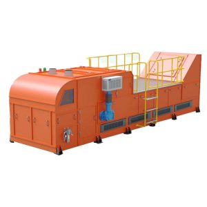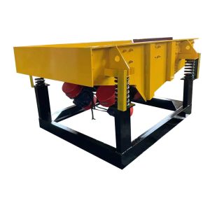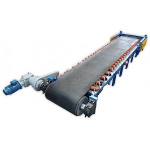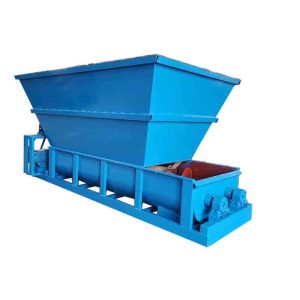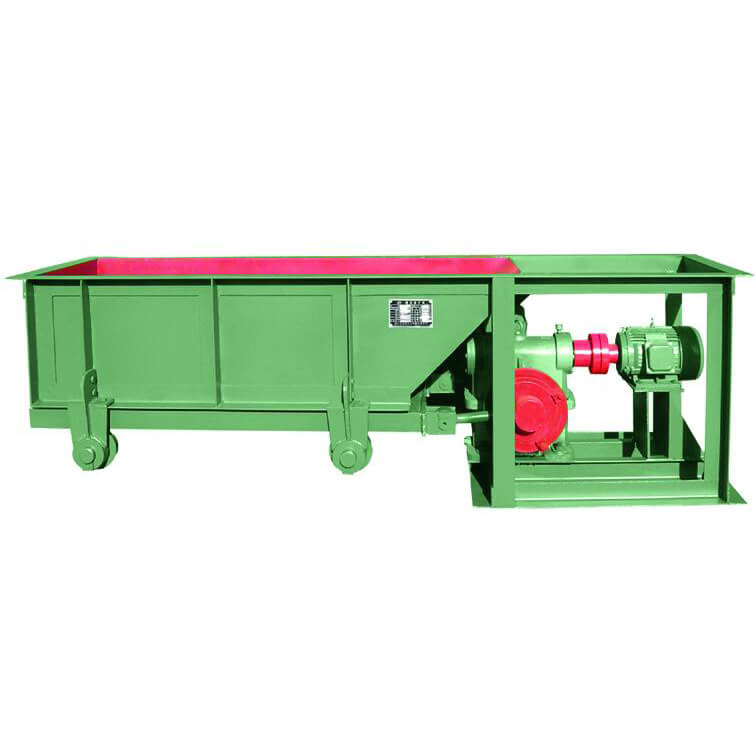
Chute Feeder
Capacity: 5-30 TPH
Max Particle: ≤350mm
Process Material: Metallurgy, mining, protection, construction, mineral processing, coal and so on.
Chute Feeder Overview
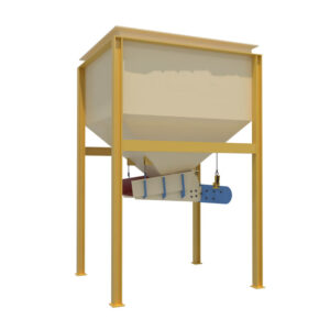
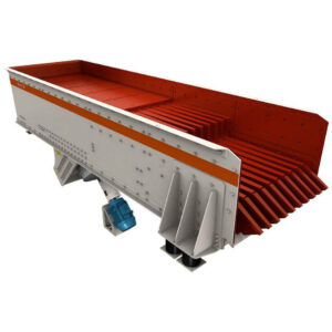
The chute feeder(also called slot type, trough feeder, swing feeder) is suitable for industrial sectors such as metallurgy, mining, protection, construction, mineral processing, coal, and so on. The blocky material is transported from the storage bin to receiving device (not suitable for transporting powder state).
A trough feeder is also known as a reciprocating or swing feeder, it is the ore storage tank discharge application earlier feeding equipment. The common feature of the structure is that it is equipped with a regulating gate that can control the height of the material layer, and the lower part of the feeding trough is a feeding board that moves back and forth. The difference is that the angle of the feed plate is different, generally 5 degrees down along the discharge direction and greater inclination (less than the static stacking angle of the material) and the angle of zero horizontal types. The action of the feeding plate includes back and forth moving type, shaking type and swinging type, etc. The transmission mechanism is of a crank-rotary type.
The trough feeder can be erected on the ground and can also be hoisted on the hopper. The flute floor is reciprocated, its punching time is 20-60 times /min, and the stroke is 20-200 mm. The stroke can be adjusted by the eccentric wheel of the driving device, and the eccentricity is half of the stroke. According to the production practice of some mines, the clay mine should not be less than 30 mm. The slot width of the feeder is about 2-2.5 times the maximum grain size of the mine. The largest trough feeder can make 500 mm. The most commonly used specification is the 980*1240 trough feeder.
Advantages
Chute Feeder Advantages
- Simple structure, even feeding, good continuous performance.
- Change and control flow and volume at any time, easy to operate adjusting to the amount of ore.
- Stable transmission, high efficiency.
- Compact structure, reasonable design.
- Excellent quality, a wide range of uses.
Structures & Working Principle
Chute Feeder Structure
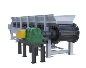
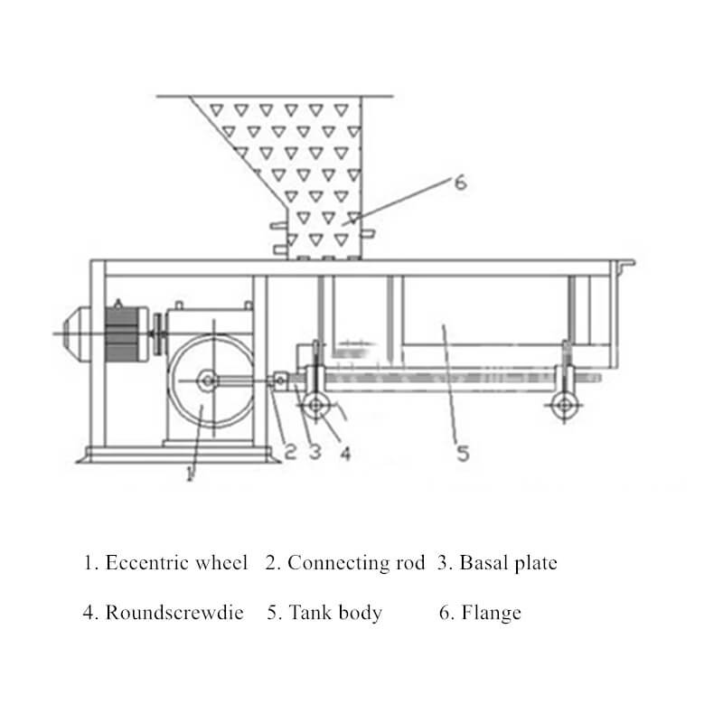
The main parts of a chute feeder include a fan Regulating Gate, feeding Trough Plate, feeding plate, roller, crank Connecting Rod, transmission device, and so on.
Chute Feeder Working Principle
The chute feeder is usually installed underneath the discharging opening of the ore bin. Minerals fall on the bushing. The bushing is located at the chute bottom, configured on the idler wheel, and via an eccentric device connected with a reducer which is linked to an electric motor by a coupler. When it works, the electric motor drives a reducer via a coupler; an eccentric disk and drain cap which is situated between the chute frame bottom and roller begins to do reciprocal and linear motion to uniformly feed minerals.
Technical Parameters
| Model | Discharge Port Size W*H (mm) | Max Feeding Size (mm) | Feeding Capacity(t/h) | Motor Power (kW) | Weight(kg) |
| 600*500 | 600*500 | 200 | 5-10 | 4 | 1045 |
| 1240*980 | 1240*980 | 350 | 10-30 | 7.5 | 1710 |

